CANBUS Troubleshooting
This document provides information on troubleshooting communication issues when using Klipper with CAN bus.
Verify CAN bus wiring
The first step in troubleshooting communication issues is to verify the CAN bus wiring.
Be sure there are exactly two 120 Ohm terminating resistors on the CAN bus. If the resistors are not properly installed then messages may not be able to be sent at all or the connection may have sporadic instability.
The CANH and CANL bus wiring should be twisted around each other. At a minimum, the wiring should have a twist every few centimeters. Avoid twisting the CANH and CANL wiring around power wires and ensure that power wires that travel parallel to the CANH and CANL wires do not have the same amount of twists.
Verify that all plugs and wire crimps on the CAN bus wiring are fully secured. Movement of the printer toolhead may jostle the CAN bus wiring causing a bad wire crimp or unsecured plug to result in intermittent communication errors.
Check for incrementing bytes_invalid counter
The Klipper log file will report a Stats line once a second when the
printer is active. These "Stats" lines will have a bytes_invalid
counter for each micro-controller. This counter should not increment
during normal printer operation (it is normal for the counter to be
non-zero after a RESTART and it is not a concern if the counter
increments once a month or so). If this counter increments on a CAN
bus micro-controller during normal printing (it increments every few
hours or more frequently) then it is an indication of a severe
problem.
Incrementing bytes_invalid on a CAN bus connection is a symptom of
reordered messages on the CAN bus. If seen, make sure to:
- Use a Linux kernel version 6.6.0 or later.
- If using a USB-to-CANBUS adapter running candlelight firmware, use v2.0 or later of candleLight_fw.
- If using Klipper's USB-to-CANBUS bridge mode, make sure the bridge node is flashed with Klipper v0.12.0 or later.
Reordered messages is a severe problem that must be fixed. It will
result in unstable behavior and can lead to confusing errors at any
part of a print. An incrementing bytes_invalid is not caused by
wiring or similar hardware issues and can only be fixed by identifying
and updating the faulty software.
Older versions of the Linux kernel had a bug in the gs_usb canbus driver code that could cause reordered canbus packets. The issue is thought to be fixed in Linux commit 24bc41b4 which was released in v6.6.0. In some cases, older Linux versions may not show the problem (due to how hardware interrupts are configured), however if problems are seen the recommended solution is to upgrade to a newer kernel.
Older versions of candlelight firmware could reorder canbus packets, and the issue is thought to be fixed in candlelight_fw commit 8b3a7b45.
Older versions of Klipper's USB-to-CANBUS bridge code could incorrectly drop canbus messages. This is not as severe as reordering messages, but it should still be fixed. It is thought to be fixed with Klipper PR #6175.
Use an appropriate txqueuelen setting
The Klipper code uses the Linux kernel to manage CAN bus traffic. By
default, the kernel will only queue 10 CAN transmit packets. It is
recommended to configure the can0 device
with a txqueuelen 128 to increase that size.
If Klipper transmits a packet and Linux has filled all of its transmit queue space then Linux will drop that packet and messages like the following will appear in the Klipper log:
Got error -1 in can write: (105)No buffer space available
Klipper will automatically retransmit the lost messages as part of its normal application level message retransmit system. Thus, this log message is a warning and it does not indicate an unrecoverable error.
If a complete CAN bus failure occurs (such as a CAN wire break) then
Linux will not be able to transmit any messages on the CAN bus and it
is common to find the above message in the Klipper log. In this case,
the log message is a symptom of a larger problem (the inability to
transmit any messages) and is not directly related to Linux
txqueuelen.
One may check the current queue size by running the Linux command ip
link show can0. It should report a bunch of text including the
snippet qlen 128. If one sees something like qlen 10 then it
indicates the CAN device has not been properly configured.
It is not recommended to use a txqueuelen significantly larger
than 128. A CAN bus running at a frequency of 1000000 will typically
take around 120us to transmit a CAN packet. Thus a queue of 128
packets is likely to take around 15-20ms to drain. A substantially
larger queue could cause excessive spikes in message round-trip-time
which could lead to unrecoverable errors. Said another way, Klipper's
application retransmit system is more robust if it does not have to
wait for Linux to drain an excessively large queue of possibly stale
data. This is analogous to the problem of
bufferbloat on internet
routers.
Under normal circumstances Klipper may utilize ~25 queue slots per
MCU - typically only utilizing more slots during retransmits.
(Specifically, the Klipper host may transmit up to 192 bytes to each
Klipper MCU before receiving an acknowledgment from that MCU.) If a
single CAN bus has 5 or more Klipper MCUs on it, then it might be
necessary to increase the txqueuelen above the recommended value
of 128. However, as above, care should be taken when selecting a new
value to avoid excessive round-trip-time latency.
Use canbus_query.py only to identify nodes never previously seen
It is only valid to use the
canbus_query.py tool
to identify micro-controllers that have never been previously
identified. Once all nodes on a bus are identified, record the
resulting uuids in the printer.cfg, and avoid running the tool
unnecessarily.
The tool is implemented using a low-level mechanism that can cause nodes to internally observe bus errors. These internal errors may result in communication interruptions and may result is some nodes disconnecting from the bus.
It is not valid to use the tool to "ping" if a node is connected. Do not run the tool during an active print.
Obtaining candump logs
The CAN bus messages sent to and from the micro-controller are handled by the Linux kernel. It is possible to capture these messages from the kernel for debugging purposes. A log of these messages may be of use in diagnostics.
The Linux can-utils tool provides the capture software. It is typically installed on a machine by running:
sudo apt-get update && sudo apt-get install can-utils
Once installed, one may obtain a capture of all CAN bus messages on an interface with the following command:
candump -tz -Ddex can0,#FFFFFFFF > mycanlog
One can view the resulting log file (mycanlog in the example above)
to see each raw CAN bus message that was sent and received by Klipper.
Understanding the content of these messages will likely require
low-level knowledge of Klipper's CANBUS protocol
and Klipper's MCU commands.
Parsing Klipper messages in a candump log
One may use the parsecandump.py tool to parse the low-level Klipper
micro-controller messages contained in a candump log. Using this tool
is an advanced topic that requires knowledge of Klipper
MCU commands. For example:
./scripts/parsecandump.py mycanlog 108 ./out/klipper.dict
This tool produces output similar to the parsedump tool. See the documentation for that tool for information on generating the Klipper micro-controller data dictionary.
In the above example, 108 is the CAN bus
id. It is a
hexadecimal number. The id 108 is assigned by Klipper to the first
micro-controller. If the CAN bus has multiple micro-controllers on it,
then the second micro-controller would be 10a, the third would be
10c, and so on.
The candump log must be produced using the -tz -Ddex command-line
arguments (for example: candump -tz -Ddex can0,#FFFFFFFF) in order
to use the parsecandump.py tool.
Using a logic analyzer on the canbus wiring
The Sigrok Pulseview software along with a low-cost logic analyzer can be useful for diagnosing CAN bus signaling. This is an advanced topic likely only of interest to experts.
One can often find "USB logic analyzers" for under $15 (US pricing as of 2023). These devices are often listed as "Saleae logic clones" or as "24MHz 8 channel USB logic analyzers".
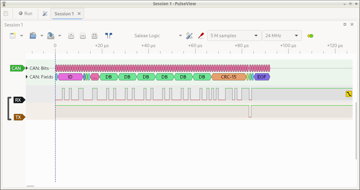
The above picture was taken while using Pulseview with a "Saleae
clone" logic analyzer. The Sigrok and Pulseview software was installed
on a desktop machine (also install the "fx2lafw" firmware if that is
packaged separately). The CH0 pin on the logic analyzer was routed to
the CAN Rx line, the CH1 pin was wired to the CAN Tx pin, and GND was
wired to GND. Pulseview was configured to only display the D0 and D1
lines (red "probe" icon center top toolbar). The number of samples was
set to 5 million (top toolbar) and the sample rate was set to 24Mhz
(top toolbar). The CAN decoder was added (yellow and green "bubble
icon" right top toolbar). The D0 channel was labeled as RX and set to
trigger on a falling edge (click on black D0 label at left). The D1
channel was labeled as TX (click on brown D1 label at left). The CAN
decoder was configured for 1Mbit rate (click on green CAN label at
left). The CAN decoder was moved to the top of the display (click and
drag green CAN label). Finally, the capture was started (click "Run"
at top left) and a packet was transmitted on the CAN bus (cansend
can0 123#121212121212).
The logic analyzer provides an independent tool for capturing packets and verifying bit timing.