Resonance Compensation
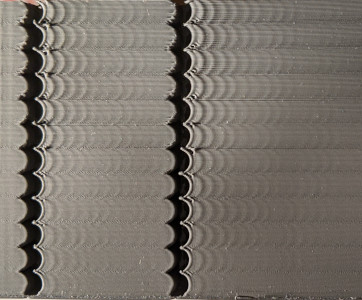
Klipper supports Input Shaping - a technique that can be used to reduce ringing (also known as echoing, ghosting or rippling) in prints. Ringing is a surface printing defect when, typically, elements like edges repeat themselves on a printed surface as a subtle 'echo':
| |
| |
|
Ringing is caused by mechanical vibrations in the printer due to quick changes of the printing direction. Note that ringing usually has mechanical origins: insufficiently rigid printer frame, non-tight or too springy belts, alignment issues of mechanical parts, heavy moving mass, etc. Those should be checked and fixed first, if possible.
Input shaping is an open-loop control technique which creates a commanding signal that cancels its own vibrations. Input shaping requires some tuning and measurements before it can be enabled. Besides ringing, Input Shaping typically reduces the vibrations and shaking of the printer in general, and may also improve the reliability of the stealthChop mode of Trinamic stepper drivers.
Tuning
Basic tuning requires measuring the ringing frequencies of the printer by printing a test model.
Slice the ringing test model, which can be found in docs/prints/ringing_tower.stl, in the slicer:
- Suggested layer height is 0.2 or 0.25 mm.
- Infill and top layers can be set to 0.
- Use 1-2 perimeters, or even better the smooth vase mode with 1-2 mm base.
- Use sufficiently high speed, around 80-100 mm/sec, for external perimeters.
- Make sure that the minimum layer time is at most 3 seconds.
- Make sure any "dynamic acceleration control" is disabled in the slicer.
- Do not turn the model. The model has X and Y marks at the back of the model. Note the unusual location of the marks vs. the axes of the printer - it is not a mistake. The marks can be used later in the tuning process as a reference, because they show which axis the measurements correspond to.
Ringing frequency
First, measure the ringing frequency.
- If
square_corner_velocityparameter was changed, revert it back to 5.0. It is not advised to increase it when using input shaper because it can cause more smoothing in parts - it is better to use higher acceleration value instead. - Disable the
minimum_cruise_ratiofeature by issuing the following command:SET_VELOCITY_LIMIT MINIMUM_CRUISE_RATIO=0 - Disable Pressure Advance:
SET_PRESSURE_ADVANCE ADVANCE=0 - If you have already added
[input_shaper]section to the printer.cfg, executeSET_INPUT_SHAPER SHAPER_FREQ_X=0 SHAPER_FREQ_Y=0command. If you get "Unknown command" error, you can safely ignore it at this point and continue with the measurements. - Execute the command:
TUNING_TOWER COMMAND=SET_VELOCITY_LIMIT PARAMETER=ACCEL START=1500 STEP_DELTA=500 STEP_HEIGHT=5Basically, we try to make ringing more pronounced by setting different large values for acceleration. This command will increase the acceleration every 5 mm starting from 1500 mm/sec^2: 1500 mm/sec^2, 2000 mm/sec^2, 2500 mm/sec^2 and so forth up until 7000 mm/sec^2 at the last band. - Print the test model sliced with the suggested parameters.
- You can stop the print earlier if the ringing is clearly visible and you see that acceleration gets too high for your printer (e.g. printer shakes too much or starts skipping steps).
-
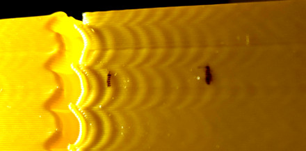
Use X and Y marks at the back of the model for reference. The measurements from the side with X mark should be used for X axis configuration, and Y mark - for Y axis configuration. Measure the distance D (in mm) between several oscillations on the part with X mark, near the notches, preferably skipping the first oscillation or two. To measure the distance between oscillations more easily, mark the oscillations first, then measure the distance between the marks with a ruler or calipers:
|
 |
| |
| -
Count how many oscillations N the measured distance D corresponds to. If you are unsure how to count the oscillations, refer to the picture above, which shows N = 6 oscillations.
- Compute the ringing frequency of X axis as V · N / D (Hz), where V is the velocity for outer perimeters (mm/sec). For the example above, we marked 6 oscillations, and the test was printed at 100 mm/sec velocity, so the frequency is 100 * 6 / 12.14 ≈ 49.4 Hz.
- Do (8) - (10) for Y mark as well.
Note that ringing on the test print should follow the pattern of the curved notches, as in the picture above. If it doesn't, then this defect is not really a ringing and has a different origin - either mechanical, or an extruder issue. It should be fixed first before enabling and tuning input shapers.
If the measurements are not reliable because, say, the distance between the oscillations is not stable, it might mean that the printer has several resonance frequencies on the same axis. One may try to follow the tuning process described in Unreliable measurements of ringing frequencies section instead and still get something out of the input shaping technique.
Ringing frequency can depend on the position of the model within the buildplate and Z height, especially on delta printers; you can check if you see the differences in frequencies at different positions along the sides of the test model and at different heights. You can calculate the average ringing frequencies over X and Y axes if that is the case.
If the measured ringing frequency is very low (below approx 20-25 Hz), it might be a good idea to invest into stiffening the printer or decreasing the moving mass - depending on what is applicable in your case - before proceeding with further input shaping tuning, and re-measuring the frequencies afterwards. For many popular printer models there are often some solutions available already.
Note that the ringing frequencies can change if the changes are made to the printer that affect the moving mass or change the stiffness of the system, for example:
- Some tools are installed, removed or replaced on the toolhead that change its mass, e.g. a new (heavier or lighter) stepper motor for direct extruder or a new hotend is installed, heavy fan with a duct is added, etc.
- Belts are tightened.
- Some addons to increase frame rigidity are installed.
- Different bed is installed on a bed-slinger printer, or glass added, etc.
If such changes are made, it is a good idea to at least measure the ringing frequencies to see if they have changed.
Input shaper configuration
After the ringing frequencies for X and Y axes are measured, you can add the
following section to your printer.cfg:
[input_shaper]
shaper_freq_x: ...  # frequency for the X mark of the test model
shaper_freq_y: ...  # frequency for the Y mark of the test model
For the example above, we get shaper_freq_x/y = 49.4.
Choosing input shaper
Klipper supports several input shapers. They differ in their sensitivity to errors determining the resonance frequency and how much smoothing they cause in the printed parts. Also, some of the shapers like 2HUMP_EI and 3HUMP_EI should usually not be used with shaper_freq = resonance frequency - they are configured from different considerations to reduce several resonances at once.
For most of the printers, either MZV or EI shapers can be recommended. This section describes a testing process to choose between them, and figure out a few other related parameters.
Print the ringing test model as follows:
- Restart the firmware:
RESTART - Prepare for test:
SET_VELOCITY_LIMIT MINIMUM_CRUISE_RATIO=0 - Disable Pressure Advance:
SET_PRESSURE_ADVANCE ADVANCE=0 - Execute:
SET_INPUT_SHAPER SHAPER_TYPE=MZV - Execute the command:
TUNING_TOWER COMMAND=SET_VELOCITY_LIMIT PARAMETER=ACCEL START=1500 STEP_DELTA=500 STEP_HEIGHT=5 - Print the test model sliced with the suggested parameters.
If you see no ringing at this point, then MZV shaper can be recommended for use.
If you do see some ringing, re-measure the frequencies using steps (8)-(10) described in Ringing frequency section. If the frequencies differ significantly from the values you obtained earlier, a more complex input shaper configuration is needed. You can refer to Technical details of Input shapers section. Otherwise, proceed to the next step.
Now try EI input shaper. To try it, repeat steps (1)-(6) from above, but
executing at step 4 the following command instead:
SET_INPUT_SHAPER SHAPER_TYPE=EI.
Compare two prints with MZV and EI input shaper. If EI shows noticeably better
results than MZV, use EI shaper, otherwise prefer MZV. Note that EI shaper will
cause more smoothing in printed parts (see the next section for further
details). Add shaper_type: mzv (or ei) parameter to [input_shaper] section,
e.g.:
[input_shaper]
shaper_freq_x: ...
shaper_freq_y: ...
shaper_type: mzv
A few notes on shaper selection:
- EI shaper may be more suited for bed slinger printers (if the resonance frequency and resulting smoothing allows): as more filament is deposited on the moving bed, the mass of the bed increases and the resonance frequency will decrease. Since EI shaper is more robust to resonance frequency changes, it may work better when printing large parts.
- Due to the nature of delta kinematics, resonance frequencies can differ a
lot in different parts of the build volume. Therefore, EI shaper can be a
better fit for delta printers rather than MZV or ZV, and should be
considered for the use. If the resonance frequency is sufficiently large
(more than 50-60 Hz), then one can even attempt to test 2HUMP_EI shaper
(by running the suggested test above with
SET_INPUT_SHAPER SHAPER_TYPE=2HUMP_EI), but check the considerations in the section below before enabling it.
Selecting max_accel
You should have a printed test for the shaper you chose from the previous step
(if you don't, print the test model sliced with the
suggested parameters with the pressure advance disabled
SET_PRESSURE_ADVANCE ADVANCE=0 and with the tuning tower enabled as
TUNING_TOWER COMMAND=SET_VELOCITY_LIMIT PARAMETER=ACCEL START=1500 STEP_DELTA=500 STEP_HEIGHT=5).
Note that at very high accelerations, depending on the resonance frequency and
the input shaper you chose (e.g. EI shaper creates more smoothing than MZV),
input shaping may cause too much smoothing and rounding of the parts. So,
max_accel should be chosen such as to prevent that. Another parameter that can
impact smoothing is square_corner_velocity, so it is not advisable to increase
it above the default 5 mm/sec to prevent increased smoothing.
In order to select a suitable max_accel value, inspect the model for the chosen input shaper. First, take a note at which acceleration ringing is still small - that you are comfortable with it.
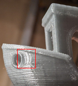
Next, check the smoothing. To help with that, the test model has a small gap in the wall (0.15 mm):

As the acceleration increases, so does the smoothing, and the actual gap in the print widens:
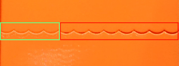
In this picture, the acceleration increases left to right, and the gap starts to grow starting from 3500 mm/sec^2 (5-th band from the left). So the good value for max_accel = 3000 (mm/sec^2) in this case to avoid the excessive smoothing.
Note the acceleration when the gap is still very small in your test print. If you see bulges, but no gap in the wall at all, even at high accelerations, it may be due to disabled Pressure Advance, especially on Bowden extruders. If that is the case, you may need to repeat the print with the PA enabled. It may also be a result of a miscalibrated (too high) filament flow, so it is a good idea to check that too.
Choose the minimum out of the two acceleration values (from ringing and
smoothing), and put it as max_accel into printer.cfg.
As a note, it may happen - especially at low ringing frequencies - that EI shaper will cause too much smoothing even at lower accelerations. In this case, MZV may be a better choice, because it may allow higher acceleration values.
At very low ringing frequencies (~25 Hz and below) even MZV shaper may create
too much smoothing. If that is the case, you can also try to repeat the
steps in Choosing input shaper section with ZV shaper,
by using SET_INPUT_SHAPER SHAPER_TYPE=ZV command instead. ZV shaper should
show even less smoothing than MZV, but is more sensitive to errors in measuring
the ringing frequencies.
Another consideration is that if a resonance frequency is too low (below 20-25 Hz), it might be a good idea to increase the printer stiffness or reduce the moving mass. Otherwise, acceleration and printing speed may be limited due too much smoothing now instead of ringing.
Fine-tuning resonance frequencies
Note that the precision of the resonance frequencies measurements using the ringing test model is sufficient for most purposes, so further tuning is not advised. If you still want to try to double-check your results (e.g. if you still see some ringing after printing a test model with an input shaper of your choice with the same frequencies as you have measured earlier), you can follow the steps in this section. Note that if you see ringing at different frequencies after enabling [input_shaper], this section will not help with that.
Assuming that you have sliced the ringing model with suggested parameters, complete the following steps for each of the axes X and Y:
- Prepare for test:
SET_VELOCITY_LIMIT MINIMUM_CRUISE_RATIO=0 - Make sure Pressure Advance is disabled:
SET_PRESSURE_ADVANCE ADVANCE=0 - Execute:
SET_INPUT_SHAPER SHAPER_TYPE=ZV - From the existing ringing test model with your chosen input shaper select
the acceleration that shows ringing sufficiently well, and set it with:
SET_VELOCITY_LIMIT ACCEL=... - Calculate the necessary parameters for the
TUNING_TOWERcommand to tuneshaper_freq_xparameter as follows: start = shaper_freq_x * 83 / 132 and factor = shaper_freq_x / 66, whereshaper_freq_xhere is the current value inprinter.cfg. - Execute the command:
TUNING_TOWER COMMAND=SET_INPUT_SHAPER PARAMETER=SHAPER_FREQ_X START=start FACTOR=factor BAND=5usingstartandfactorvalues calculated at step (5). - Print the test model.
- Reset the original frequency value:
SET_INPUT_SHAPER SHAPER_FREQ_X=.... - Find the band which shows ringing the least and count its number from the bottom starting at 1.
- Calculate the new shaper_freq_x value via old shaper_freq_x * (39 + 5 * #band-number) / 66.
Repeat these steps for the Y axis in the same manner, replacing references to X
axis with the axis Y (e.g. replace shaper_freq_x with shaper_freq_y in
the formulae and in the TUNING_TOWER command).
As an example, let's assume you have had measured the ringing frequency for one
of the axis equal to 45 Hz. This gives start = 45 * 83 / 132 = 28.30
and factor = 45 / 66 = 0.6818 values for TUNING_TOWER command.
Now let's assume that after printing the test model, the fourth band from the
bottom gives the least ringing. This gives the updated shaper_freq_? value
equal to 45 * (39 + 5 * 4) / 66 ≈ 40.23.
After both new shaper_freq_x and shaper_freq_y parameters have been
calculated, you can update [input_shaper] section in printer.cfg with the
new shaper_freq_x and shaper_freq_y values.
Pressure Advance
If you use Pressure Advance, it may need to be re-tuned. Follow the instructions to find the new value, if it differs from the previous one. Make sure to restart Klipper before tuning Pressure Advance.
Unreliable measurements of ringing frequencies
If you are unable to measure the ringing frequencies, e.g. if the distance between the oscillations is not stable, you may still be able to take advantage of input shaping techniques, but the results may not be as good as with proper measurements of the frequencies, and will require a bit more tuning and printing the test model. Note that another possibility is to purchase and install an accelerometer and measure the resonances with it (refer to the docs describing the required hardware and the setup process) - but this option requires some crimping and soldering.
For tuning, add empty [input_shaper] section to your
printer.cfg. Then, assuming that you have sliced the ringing model
with suggested parameters, print the test model 3 times as
follows. First time, prior to printing, run
RESTARTSET_VELOCITY_LIMIT MINIMUM_CRUISE_RATIO=0SET_PRESSURE_ADVANCE ADVANCE=0SET_INPUT_SHAPER SHAPER_TYPE=2HUMP_EI SHAPER_FREQ_X=60 SHAPER_FREQ_Y=60TUNING_TOWER COMMAND=SET_VELOCITY_LIMIT PARAMETER=ACCEL START=1500 STEP_DELTA=500 STEP_HEIGHT=5
and print the model. Then print the model again, but before printing run instead
SET_INPUT_SHAPER SHAPER_TYPE=2HUMP_EI SHAPER_FREQ_X=50 SHAPER_FREQ_Y=50TUNING_TOWER COMMAND=SET_VELOCITY_LIMIT PARAMETER=ACCEL START=1500 STEP_DELTA=500 STEP_HEIGHT=5
Then print the model for the 3rd time, but now run
SET_INPUT_SHAPER SHAPER_TYPE=2HUMP_EI SHAPER_FREQ_X=40 SHAPER_FREQ_Y=40TUNING_TOWER COMMAND=SET_VELOCITY_LIMIT PARAMETER=ACCEL START=1500 STEP_DELTA=500 STEP_HEIGHT=5
Essentially, we are printing the ringing test model with TUNING_TOWER using 2HUMP_EI shaper with shaper_freq = 60 Hz, 50 Hz, and 40 Hz.
If none of the models demonstrate improvements in ringing, then, unfortunately, it does not look like the input shaping techniques can help with your case.
Otherwise, it may be that all models show no ringing, or some show the ringing and some - not so much. Choose the test model with the highest frequency that still shows good improvements in ringing. For example, if 40 Hz and 50 Hz models show almost no ringing, and 60 Hz model already shows some more ringing, stick with 50 Hz.
Now check if EI shaper would be good enough in your case. Choose EI shaper frequency based on the frequency of 2HUMP_EI shaper you chose:
- For 2HUMP_EI 60 Hz shaper, use EI shaper with shaper_freq = 50 Hz.
- For 2HUMP_EI 50 Hz shaper, use EI shaper with shaper_freq = 40 Hz.
- For 2HUMP_EI 40 Hz shaper, use EI shaper with shaper_freq = 33 Hz.
Now print the test model one more time, running
SET_INPUT_SHAPER SHAPER_TYPE=EI SHAPER_FREQ_X=... SHAPER_FREQ_Y=...TUNING_TOWER COMMAND=SET_VELOCITY_LIMIT PARAMETER=ACCEL START=1500 STEP_DELTA=500 STEP_HEIGHT=5
providing the shaper_freq_x=... and shaper_freq_y=... as determined previously.
If EI shaper shows very comparable good results as 2HUMP_EI shaper, stick with
EI shaper and the frequency determined earlier, otherwise use 2HUMP_EI shaper
with the corresponding frequency. Add the results to printer.cfg as, e.g.
[input_shaper]
shaper_freq_x: 50
shaper_freq_y: 50
shaper_type: 2hump_ei
Continue the tuning with Selecting max_accel section.
Troubleshooting and FAQ
I cannot get reliable measurements of resonance frequencies
First, make sure it is not some other problem with the printer instead of ringing. If the measurements are not reliable because, say, the distance between the oscillations is not stable, it might mean that the printer has several resonance frequencies on the same axis. One may try to follow the tuning process described in Unreliable measurements of ringing frequencies section and still get something out of the input shaping technique. Another possibility is to install an accelerometer, measure the resonances with it, and auto-tune the input shaper using the results of those measurements.
After enabling [input_shaper], I get too smoothed printed parts and fine details are lost
Check the considerations in Selecting max_accel section. If the resonance frequency is low, one should not set too high max_accel or increase square_corner_velocity parameters. It might also be better to choose MZV or even ZV input shapers over EI (or 2HUMP_EI and 3HUMP_EI shapers).
After successfully printing for some time without ringing, it appears to come back
It is possible that after some time the resonance frequencies have changed. E.g. maybe the belts tension has changed (belts got more loose), etc. It is a good idea to check and re-measure the ringing frequencies as described in Ringing frequency section and update your config file if necessary.
Is dual carriage setup supported with input shapers?
Yes. In this case, one should measure the resonances twice for each carriage.
For example, if the second (dual) carriage is installed on X axis, it is
possible to set different input shapers for X axis for the primary and dual
carriages. However, the input shaper for Y axis should be the same for both
carriages (as ultimately this axis is driven by one or more stepper motors each
commanded to perform exactly the same steps). One possibility to configure
the input shaper for such setups is to keep [input_shaper] section empty and
additionally define a [delayed_gcode] section in the printer.cfg as follows:
[input_shaper]
# Intentionally empty

[delayed_gcode init_shaper]
initial_duration: 0.1
gcode:
  SET_DUAL_CARRIAGE CARRIAGE=1
  SET_INPUT_SHAPER SHAPER_TYPE_X=<dual_carriage_shaper> SHAPER_FREQ_X=<dual_carriage_freq> SHAPER_TYPE_Y=<y_shaper> SHAPER_FREQ_Y=<y_freq>
  SET_DUAL_CARRIAGE CARRIAGE=0
  SET_INPUT_SHAPER SHAPER_TYPE_X=<primary_carriage_shaper> SHAPER_FREQ_X=<primary_carriage_freq> SHAPER_TYPE_Y=<y_shaper> SHAPER_FREQ_Y=<y_freq>
Note that SHAPER_TYPE_Y and SHAPER_FREQ_Y should be the same in both
commands. It is also possible to put a similar snippet into the start g-code
in the slicer, however then the shaper will not be enabled until any print
is started.
Note that the input shaper only needs to be configured once. Subsequent changes
of the carriages or their modes via SET_DUAL_CARRIAGE command will preserve
the configured input shaper parameters.
Does input_shaper affect print time?
No, input_shaper feature has pretty much no impact on the print times by
itself. However, the value of max_accel certainly does (tuning of this
parameter described in this section).
Technical details
Input shapers
Input shapers used in Klipper are rather standard, and one can find more in-depth overview in the articles describing the corresponding shapers. This section contains a brief overview of some technical aspects of the supported input shapers. The table below shows some (usually approximate) parameters of each shaper.
| Input shaper |
Shaper duration |
Vibration reduction 20x (5% vibration tolerance) |
Vibration reduction 10x (10% vibration tolerance) |
|---|---|---|---|
| ZV | 0.5 / shaper_freq | N/A | ± 5% shaper_freq |
| MZV | 0.75 / shaper_freq | ± 4% shaper_freq | -10%...+15% shaper_freq |
| ZVD | 1 / shaper_freq | ± 15% shaper_freq | ± 22% shaper_freq |
| EI | 1 / shaper_freq | ± 20% shaper_freq | ± 25% shaper_freq |
| 2HUMP_EI | 1.5 / shaper_freq | ± 35% shaper_freq | ± 40 shaper_freq |
| 3HUMP_EI | 2 / shaper_freq | -45...+50% shaper_freq | -50%...+55% shaper_freq |
A note on vibration reduction: the values in the table above are approximate. If the damping ratio of the printer is known for each axis, the shaper can be configured more precisely and it will then reduce the resonances in a bit wider range of frequencies. However, the damping ratio is usually unknown and is hard to estimate without a special equipment, so Klipper uses 0.1 value by default, which is a good all-round value. The frequency ranges in the table cover a number of different possible damping ratios around that value (approx. from 0.05 to 0.2).
Also note that EI, 2HUMP_EI, and 3HUMP_EI are tuned to reduce vibrations to 5%, so the values for 10% vibration tolerance are provided only for the reference.
How to use this table:
- Shaper duration affects the smoothing in parts - the larger it is, the more smooth the parts are. This dependency is not linear, but can give a sense of which shapers 'smooth' more for the same frequency. The ordering by smoothing is like this: ZV < MZV < ZVD ≈ EI < 2HUMP_EI < 3HUMP_EI. Also, it is rarely practical to set shaper_freq = resonance freq for shapers 2HUMP_EI and 3HUMP_EI (they should be used to reduce vibrations for several frequencies).
- One can estimate a range of frequencies in which the shaper reduces vibrations. For example, MZV with shaper_freq = 35 Hz reduces vibrations to 5% for frequencies [33.6, 36.4] Hz. 3HUMP_EI with shaper_freq = 50 Hz reduces vibrations to 5% in range [27.5, 75] Hz.
- One can use this table to check which shaper they should be using if they need to reduce vibrations at several frequencies. For example, if one has resonances at 35 Hz and 60 Hz on the same axis: a) EI shaper needs to have shaper_freq = 35 / (1 - 0.2) = 43.75 Hz, and it will reduce resonances until 43.75 * (1 + 0.2) = 52.5 Hz, so it is not sufficient; b) 2HUMP_EI shaper needs to have shaper_freq = 35 / (1 - 0.35) = 53.85 Hz and will reduce vibrations until 53.85 * (1 + 0.35) = 72.7 Hz - so this is an acceptable configuration. Always try to use as high shaper_freq as possible for a given shaper (perhaps with some safety margin, so in this example shaper_freq ≈ 50-52 Hz would work best), and try to use a shaper with as small shaper duration as possible.
- If one needs to reduce vibrations at several very different frequencies (say, 30 Hz and 100 Hz), they may see that the table above does not provide enough information. In this case one may have more luck with scripts/graph_shaper.py script, which is more flexible.