Kinematics
This document provides an overview of how Klipper implements robot motion (its kinematics). The contents may be of interest to both developers interested in working on the Klipper software as well as users interested in better understanding the mechanics of their machines.
Acceleration
Klipper implements a constant acceleration scheme whenever the print head changes velocity - the velocity is gradually changed to the new speed instead of suddenly jerking to it. Klipper always enforces acceleration between the tool head and the print. The filament leaving the extruder can be quite fragile - rapid jerks and/or extruder flow changes lead to poor quality and poor bed adhesion. Even when not extruding, if the print head is at the same level as the print then rapid jerking of the head can cause disruption of recently deposited filament. Limiting speed changes of the print head (relative to the print) reduces risks of disrupting the print.
It is also important to limit acceleration so that the stepper motors do not skip or put excessive stress on the machine. Klipper limits the torque on each stepper by virtue of limiting the acceleration of the print head. Enforcing acceleration at the print head naturally also limits the torque of the steppers that move the print head (the inverse is not always true).
Klipper implements constant acceleration. The key formula for constant acceleration is:
velocity(time) = start_velocity + accel*time
Trapezoid generator
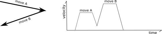
Klipper uses a traditional "trapezoid generator" to model the motion of each move - each move has a start speed, it accelerates to a cruising speed at constant acceleration, it cruises at a constant speed, and then decelerates to the end speed using constant acceleration.
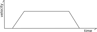
It's called a "trapezoid generator" because a velocity diagram of the move looks like a trapezoid.
The cruising speed is always greater than or equal to both the start speed and the end speed. The acceleration phase may be of zero duration (if the start speed is equal to the cruising speed), the cruising phase may be of zero duration (if the move immediately starts decelerating after acceleration), and/or the deceleration phase may be of zero duration (if the end speed is equal to the cruising speed).
Look-ahead
The "look-ahead" system is used to determine cornering speeds between moves.
Consider the following two moves contained on an XY plane:
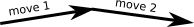
In the above situation it is possible to fully decelerate after the first move and then fully accelerate at the start of the next move, but that is not ideal as all that acceleration and deceleration would greatly increase the print time and the frequent changes in extruder flow would result in poor print quality.
To solve this, the "look-ahead" mechanism queues multiple incoming moves and analyzes the angles between moves to determine a reasonable speed that can be obtained during the "junction" between two moves. If the next move is nearly in the same direction then the head need only slow down a little (if at all).
However, if the next move forms an acute angle (the head is going to travel in nearly a reverse direction on the next move) then only a small junction speed is permitted.
The junction speeds are determined using "approximated centripetal acceleration". Best described by the author. However, in Klipper, junction speeds are configured by specifying the desired speed that a 90° corner should have (the "square corner velocity"), and the junction speeds for other angles are derived from that.
Key formula for look-ahead:
end_velocity^2 = start_velocity^2 + 2*accel*move_distance
Minimum cruise ratio
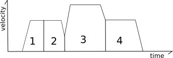
Klipper also implements a mechanism for smoothing out the motions of short "zigzag" moves. Consider the following moves:
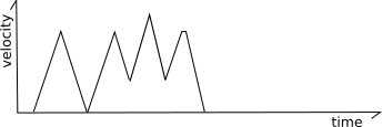
In the above, the frequent changes from acceleration to deceleration can cause the machine to vibrate which causes stress on the machine and increases the noise. Klipper implements a mechanism to ensure there is always some movement at a cruising speed between acceleration and deceleration. This is done by reducing the top speed of some moves (or sequence of moves) to ensure there is a minimum distance traveled at cruising speed relative to the distance traveled during acceleration and deceleration.
Klipper implements this feature by tracking both a regular move acceleration as well as a virtual "acceleration to deceleration" rate:
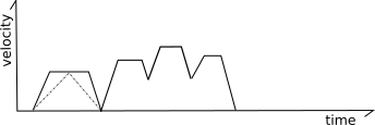
Specifically, the code calculates what the velocity of each move would be if it were limited to this virtual "acceleration to deceleration" rate. In the above picture the dashed gray lines represent this virtual acceleration rate for the first move. If a move can not reach its full cruising speed using this virtual acceleration rate then its top speed is reduced to the maximum speed it could obtain at this virtual acceleration rate.
For most moves the limit will be at or above the move's existing limits and no change in behavior is induced. For short zigzag moves, however, this limit reduces the top speed. Note that it does not change the actual acceleration within the move - the move continues to use the normal acceleration scheme up to its adjusted top-speed.
Generating steps
Once the look-ahead process completes, the print head movement for the given move is fully known (time, start position, end position, velocity at each point) and it is possible to generate the step times for the move. This process is done within "kinematic classes" in the Klipper code. Outside of these kinematic classes, everything is tracked in millimeters, seconds, and in cartesian coordinate space. It's the task of the kinematic classes to convert from this generic coordinate system to the hardware specifics of the particular printer.
Klipper uses an iterative solver to generate the step times for each stepper. The code contains the formulas to calculate the ideal cartesian coordinates of the head at each moment in time, and it has the kinematic formulas to calculate the ideal stepper positions based on those cartesian coordinates. With these formulas, Klipper can determine the ideal time that the stepper should be at each step position. The given steps are then scheduled at these calculated times.
The key formula to determine how far a move should travel under constant acceleration is:
move_distance = (start_velocity + .5 * accel * move_time) * move_time
and the key formula for movement with constant velocity is:
move_distance = cruise_velocity * move_time
The key formulas for determining the cartesian coordinate of a move given a move distance is:
cartesian_x_position = start_x + move_distance * total_x_movement / total_movement
cartesian_y_position = start_y + move_distance * total_y_movement / total_movement
cartesian_z_position = start_z + move_distance * total_z_movement / total_movement
Cartesian Robots
Generating steps for cartesian printers is the simplest case. The movement on each axis is directly related to the movement in cartesian space.
Key formulas:
stepper_x_position = cartesian_x_position
stepper_y_position = cartesian_y_position
stepper_z_position = cartesian_z_position
CoreXY Robots
Generating steps on a CoreXY machine is only a little more complex than basic cartesian robots. The key formulas are:
stepper_a_position = cartesian_x_position + cartesian_y_position
stepper_b_position = cartesian_x_position - cartesian_y_position
stepper_z_position = cartesian_z_position
Delta Robots
Step generation on a delta robot is based on Pythagoras's theorem:
stepper_position = (sqrt(arm_length^2

                         - (cartesian_x_position - tower_x_position)^2
                         - (cartesian_y_position - tower_y_position)^2)
                    + cartesian_z_position)
Stepper motor acceleration limits
With delta kinematics it is possible for a move that is accelerating in cartesian space to require an acceleration on a particular stepper motor greater than the move's acceleration. This can occur when a stepper arm is more horizontal than vertical and the line of movement passes near that stepper's tower. Although these moves could require a stepper motor acceleration greater than the printer's maximum configured move acceleration, the effective mass moved by that stepper would be smaller. Thus the higher stepper acceleration does not result in significantly higher stepper torque and it is therefore considered harmless.
However, to avoid extreme cases, Klipper enforces a maximum ceiling on stepper acceleration of three times the printer's configured maximum move acceleration. (Similarly, the maximum velocity of the stepper is limited to three times the maximum move velocity.) In order to enforce this limit, moves at the extreme edge of the build envelope (where a stepper arm may be nearly horizontal) will have a lower maximum acceleration and velocity.
Extruder kinematics
Klipper implements extruder motion in its own kinematic class. Since the timing and speed of each print head movement is fully known for each move, it's possible to calculate the step times for the extruder independently from the step time calculations of the print head movement.
Basic extruder movement is simple to calculate. The step time generation uses the same formulas that cartesian robots use:
stepper_position = requested_e_position
Pressure advance
Experimentation has shown that it's possible to improve the modeling of the extruder beyond the basic extruder formula. In the ideal case, as an extrusion move progresses, the same volume of filament should be deposited at each point along the move and there should be no volume extruded after the move. Unfortunately, it's common to find that the basic extrusion formulas cause too little filament to exit the extruder at the start of extrusion moves and for excess filament to extrude after extrusion ends. This is often referred to as "ooze".
The "pressure advance" system attempts to account for this by using a different model for the extruder. Instead of naively believing that each mm^3 of filament fed into the extruder will result in that amount of mm^3 immediately exiting the extruder, it uses a model based on pressure. Pressure increases when filament is pushed into the extruder (as in Hooke's law) and the pressure necessary to extrude is dominated by the flow rate through the nozzle orifice (as in Poiseuille's law). The key idea is that the relationship between filament, pressure, and flow rate can be modeled using a linear coefficient:
pa_position = nominal_position + pressure_advance_coefficient * nominal_velocity
See the pressure advance document for information on how to find this pressure advance coefficient.
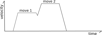
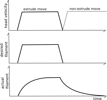
The basic pressure advance formula can cause the extruder motor to make sudden velocity changes. Klipper implements "smoothing" of the extruder movement to avoid this.
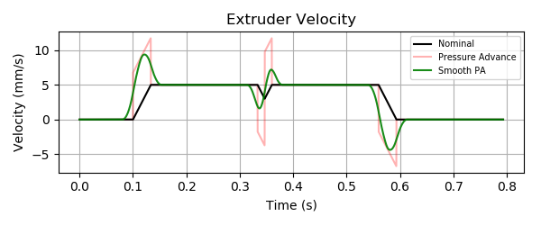
The above graph shows an example of two extrusion moves with a non-zero cornering velocity between them. Note that the pressure advance system causes additional filament to be pushed into the extruder during acceleration. The higher the desired filament flow rate, the more filament must be pushed in during acceleration to account for pressure. During head deceleration the extra filament is retracted (the extruder will have a negative velocity).
The "smoothing" is implemented using a weighted average of the
extruder position over a small time period (as specified by the
pressure_advance_smooth_time config parameter). This averaging can
span multiple g-code moves. Note how the extruder motor will start
moving prior to the nominal start of the first extrusion move and will
continue to move after the nominal end of the last extrusion move.
Key formula for "smoothed pressure advance":
smooth_pa_position(t) =
    ( definitive_integral(pa_position(x) * (smooth_time/2 - abs(t - x)) * dx,
                          from=t-smooth_time/2, to=t+smooth_time/2)
     / (smooth_time/2)^2 )