共振值测量
Klipper has built-in support for the ADXL345, MPU-9250, LIS2DW and LIS3DH compatible accelerometers which can be used to measure resonance frequencies of the printer for different axes, and auto-tune input shapers to compensate for resonances. Note that using accelerometers requires some soldering and crimping. The ADXL345 can be connected to the SPI interface of a Raspberry Pi or MCU board (it needs to be reasonably fast). The MPU family can be connected to the I2C interface of a Raspberry Pi directly, or to an I2C interface of an MCU board that supports 400kbit/s fast mode in Klipper. The LIS2DW and LIS3DH can be connected to either SPI or I2C with the same considerations as above.
When sourcing accelerometers, be aware that there are a variety of different PCB board designs and different clones of them. If it is going to be connected to a 5V printer MCU ensure it has a voltage regulator and level shifters.
For ADXL345s, make sure that the board supports SPI mode (a small number of boards appear to be hard-configured for I2C by pulling SDO to GND).
For MPU-9250/MPU-9255/MPU-6515/MPU-6050/MPU-6500/ICM20948s and LIS2DW/LIS3DH there are also a variety of board designs and clones with different I2C pull-up resistors which will need supplementing.
MCUs with Klipper I2C fast-mode Support
| MCU Family | 微控制器(S)测试 | 支持的微控制器(S) |
|---|---|---|
| Raspberry Pi | 3B+, Pico | 3A, 3A+, 3B, 4 |
| AVR解锁 | ATmega328p | ATmega32u4, ATmega128, ATmega168, ATmega328, ATmega644p, ATmega1280, ATmega1284, ATmega2560 |
| AVR AT90 | - | AT90usb646, AT90usb1286 |
| SAMD | SAMC21G18 | SAMC21G18, SAMD21G18, SAMD21E18, SAMD21J18, SAMD21E15, SAMD51G19, SAMD51J19, SAMD51N19, SAMD51P20, SAME51J19, SAME51N19, SAME54P20 |
安装指南
接线
建议使用带有屏蔽双绞线(CAT5e或更好的)的以太网电缆,以实现远距离信号的完整性。如果您仍然遇到信号完整性问题(SPI/I2C错误):
- 用数字万用表仔细检查接线:
- 关闭时正确连接(连续性)
- 正确的电源和接地电压
- 仅限I2C:
- 检查SCL和SDA线路的3.3V电阻是否在900欧姆到1.8K的范围内
- 有关完整的技术细节,请参考I2C-Bus规范的第7章和FAST-MODE的用户手册UM10204
- 缩短电缆
仅将以太网电缆屏蔽连接到MCU板/PI接地。
通电前请仔细检查接线,以防止损坏您的MCU/树莓PI或加速度计。
SPI加速度计
三条双绞线的建议双绞线顺序:
GND+MISO
3.3V+MOSI
SCLK +CS
请注意,与电缆屏蔽不同,GND必须在两端连接。
ADXL345
Direct to Raspberry Pi
注:许多MCU将在SPI模式下使用ADXL345(例如PI Pico),布线和配置将根据您的特定主板和可用的引脚而有所不同。
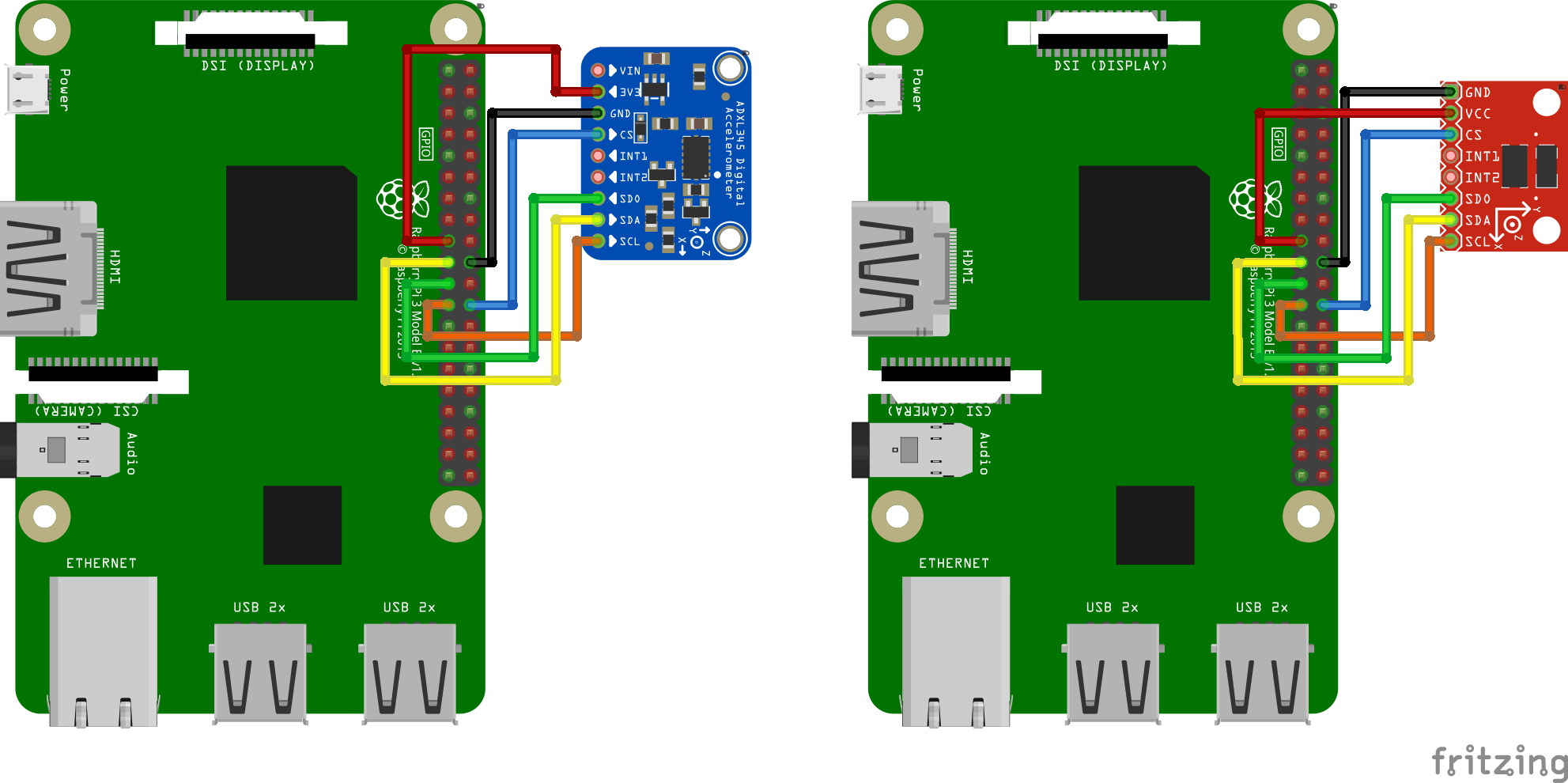
我们需要将ADXL345连接到树莓派的SPI接口。注意,尽管ADXL345文档推荐使用I2C,但其数据吞吐能力不足,不能实现共振测量的要求。推荐的接线图为:
| ADXL345引脚 | 树莓派引脚 | 树莓派引脚名称 |
|---|---|---|
| 3V3 或 VCC | 01 | 3.3V DC power |
| GND | 06 | 地(GND) |
| CS | 24 | GPIO08 (SPI0_CE0_N) |
| SDO | 21 | GPIO09 (SPI0_MISO) |
| SDA | 19 | GPIO10 (SPI0_MOSI) |
| SCL | 23 | GPIO11 (SPI0_SCLK) |
部分ADXL345开发板的Fritzing接线图如下:
Using Raspberry Pi Pico
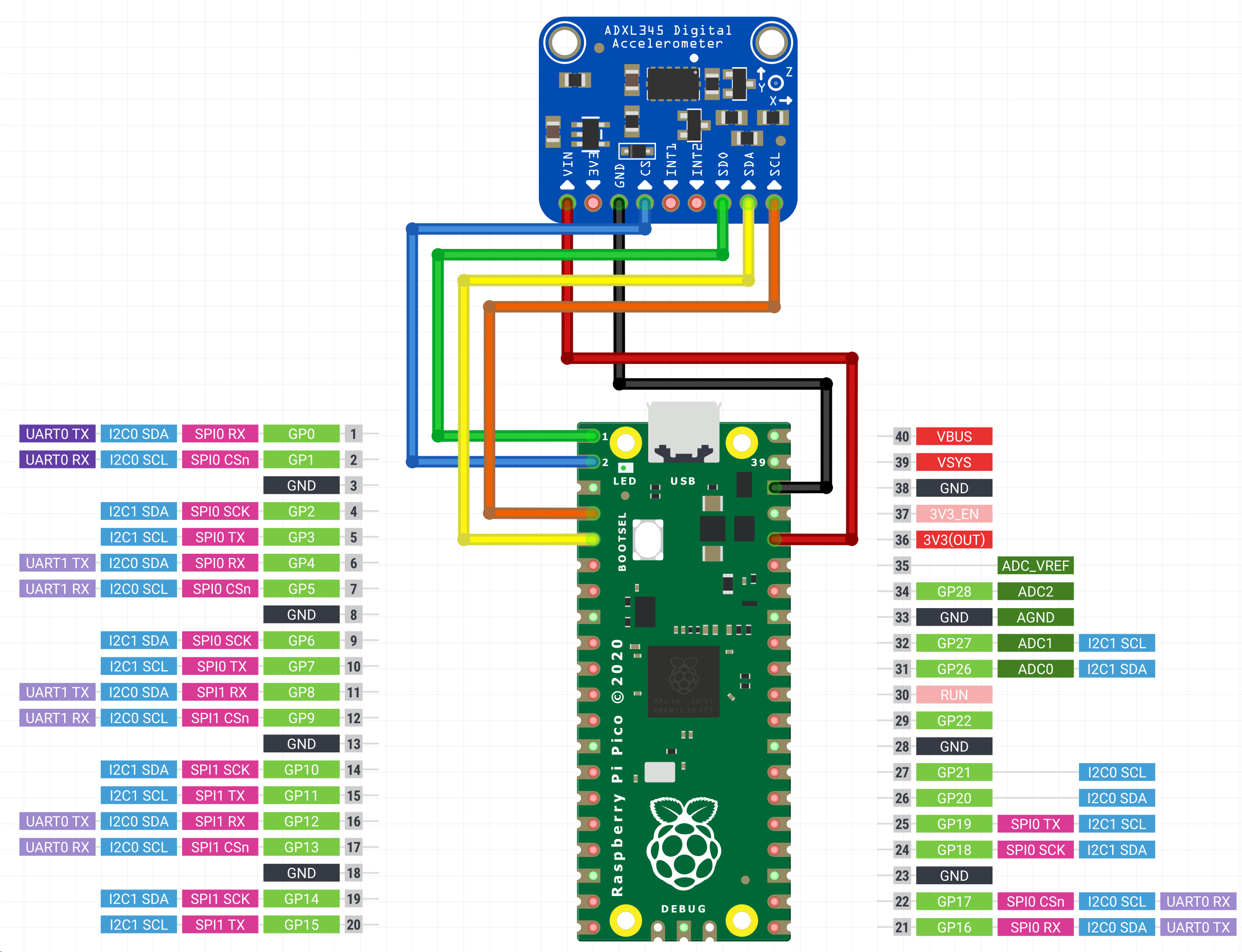
You may connect the ADXL345 to your Raspberry Pi Pico and then connect the Pico to your Raspberry Pi via USB. This makes it easy to reuse the accelerometer on other Klipper devices, as you can connect via USB instead of GPIO. The Pico does not have much processing power, so make sure it is only running the accelerometer and not performing any other duties.
In order to avoid damage to your RPi make sure to connect the ADXL345 to 3.3V only. Depending on the board's layout, a level shifter may be present, which makes 5V dangerous for your RPi.
| ADXL345引脚 | Pico pin | Pico pin name |
|---|---|---|
| 3V3 或 VCC | 36 | 3.3V DC power |
| GND | 388 | 地(GND) |
| CS | 2 | GP1 (SPI0_CSn) |
| SDO | 1 | GP0 (SPI0_RX) |
| SDA | 5 | GP3 (SPI0_TX) |
| SCL | 4 | GP2 (SPI0_SCK) |
Wiring diagrams for some of the ADXL345 boards:
I2C加速度计
建议的三对双绞线顺序(首选):
3.3V+GND
SDA+GND
SCL+GND
或用于两对:
3.3V+SDA
GND+SCL
请注意,与电缆屏蔽不同,任何接地网(S)都应在两端连接。
MPU-9250/MPU-9255/MPU-6515/MPU-6050/MPU-6500/ICM20948
这些加速度计已在RPI、RP2040(Pico)和AVR上以400kbit/S(快速模式)的I2C模式工作。一些MPU加速度计模块包括上拉,但有些模块在10K时太大,必须更换或补充较小的并联电阻。
推荐的树莓派上的I2C连接方案:
| MPU-9250引脚 | 树莓派引脚 | 树莓派引脚名称 |
|---|---|---|
| VCC | 01 | 3.3v 直流(DC)电源 |
| GND | 09 | 地(GND) |
| SDA | 03 | GPIO02(SDA1) |
| SCL | 05 | GPIO03 (SCL1) |
RPI在SCL和SDA上都有1.8k的Bit-in引体向上。
RP2040上I2C(I2c0a)的建议连接方案:
| MPU-9250引脚 | RP2040引脚 | RP2040引脚名称 |
|---|---|---|
| VCC | 36 | 3v3 |
| GND | 388 | 地(GND) |
| SDA | 01 | GP0 (I2C0 SDA) |
| SCL | 02 | GP1 (I2C0 SCL) |
Pico不包括任何内置I2C上拉电阻。
AVR ATmega328P Arduino Nano上I2C(TWI)的建议连接方案:
| MPU-9250引脚 | Atmega 328P TQFP 32针脚 | Atmega 328P端号名称 | Arduino纳米针 |
|---|---|---|---|
| VCC | 39 | - | - |
| GND | 388 | 地(GND) | GND |
| SDA | 27 | SDA | A4 |
| SCL | 28 | SCL | A5 |
Arduino Nano不包括任何内置上拉电阻,也不包括3.3V电源插针。
固定加速度传感器
加速度传感器应固定在打印头上。应根据打印机的情况设计合适的固定件。推荐将加速度的测量轴与打印机运行轴的方向进行对齐。然而,如果轴对齐极其麻烦,可以将打印机的轴使用其他测量轴对齐,比如打印机+X对应传感器-X,甚至打印机+X对应传感器-Z等。
下面是ADXL345固定到SmartEffector的示例:
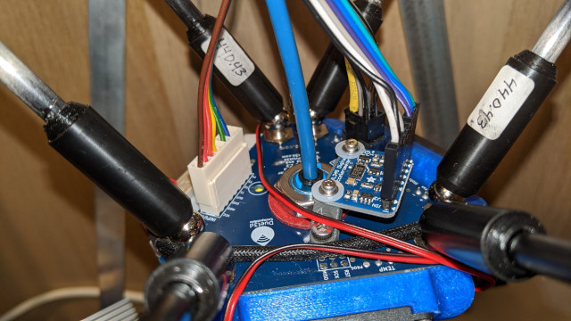
注意,滑床式打印机需要设计两个固定件:一个安装于打印头,另一个用于热床,并进行两次测量。详见 对应分节。
注意!:务必确保加速度传感器和任何螺丝都不应该接触到打印机的金属部分。紧固件必须设计成在加速度传感器和打印机框体间形成电气绝缘。错误的设计可能会形成短路,从而损坏电气元件。
软件设置
请注意,共振测量和整形器自动校准需要默认情况下不安装的其他软件依赖项。首先,在你的树莓派上运行以下命令:
sudo apt update
sudo apt install python3-numpy python3-matplotlib libatlas-base-dev libopenblas-dev
接下来,为了在Klipper环境中安装NumPy,运行命令:
~/klippy-env/bin/pip install -v "numpy<1.26"
Note that, depending on the performance of the CPU, it may take a lot of time, up to 10-20 minutes. Be patient and wait for the completion of the installation. On some occasions, if the board has too little RAM the installation may fail and you will need to enable swap. Also note the forced version, due to newer versions of NumPY having requirements that may not be satisfied in some klipper python environments.
Once installed please check that no errors show from the command:
~/klippy-env/bin/python -c 'import numpy;'
The correct output should simply be a new line.
使用RPI配置ADXL345
首先,检查并按照RPI微控制器文档中的说明在Raspberry PI上设置“Linux MCU”。这将配置在您的PI上运行的第二个Klipper实例。
通过运行sudo raspi-config 后的 "Interfacing options"菜单中启用 SPI 以确保Linux SPI 驱动已启用。
在printer.cfg中添加以下内容:
[MCU RPI]。
序列:/tmp/Klipper_host_mcu。

[adx1345]。
CS_PIN:RPI:无。

[共振测试仪]。
加速芯片:adxl345。
探测点(_P):
100、100、20#一个例子
建议在测试开始前,用探针在热床中央进行一次探测,触发后稍微上移。
Configure ADXL345 With Pi Pico
Flash the Pico Firmware
On your Raspberry Pi, compile the firmware for the Pico.
cd ~/klipper
make clean
make menuconfig
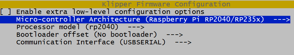
Now, while holding down the BOOTSEL button on the Pico, connect the Pico to the Raspberry Pi via USB. Compile and flash the firmware.
make flash FLASH_DEVICE=first
If that fails, you will be told which FLASH_DEVICE to use. In this example, that's make flash FLASH_DEVICE=2e8a:0003. 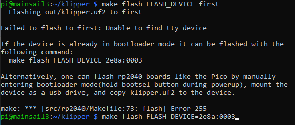
Configure the Connection
The Pico will now reboot with the new firmware and should show up as a serial device. Find the pico serial device with ls /dev/serial/by-id/*. You can now add an adxl.cfg file with the following settings:
[mcu adxl]
# Change <mySerial> to whatever you found above. For example,
# usb-Klipper_rp2040_E661640843545B2E-if00
serial: /dev/serial/by-id/usb-Klipper_rp2040_<mySerial>

[adxl345]
cs_pin: adxl:gpio1
spi_bus: spi0a
axes_map: x,z,y

[resonance_tester]
accel_chip: adxl345
probe_points:
    # Somewhere slightly above the middle of your print bed
    147,154, 20

[output_pin power_mode] # Improve power stability
pin: adxl:gpio23
If setting up the ADXL345 configuration in a separate file, as shown above, you'll also want to modify your printer.cfg file to include this:
[include adxl.cfg] # Comment this out when you disconnect the accelerometer
通过RESTART命令重启Klipper。
Configure LIS2DW series over SPI
[MCU列表]。
#将<mySerial>更改为您在上面找到的任何内容。例如,。
#usb-klipper_rp2040_E661640843545B2E-if00。
序列号:/dev/serial/by-id/usb-Klipper_rp2040_<mySerial>。

[lis2dw]。
Cs_pin:lis:gpio1。
SPI_BUS:SP0A。
AXES_MAP:x、z、y。

[共振测试仪]。
加速芯片:lis2dw。
探测点(_P):
#在你的打印床中间稍高一点的地方。
147,154,20
Configure MPU-6000/9000 series With RPi
Make sure the Linux I2C driver is enabled and the baud rate is set to 400000 (see Enabling I2C section for more details). Then, add the following to the printer.cfg:
[MCU RPI]。
序列:/tmp/Klipper_host_mcu。

[mpu9250]。
I2C_MCU:RPI。
I2C_BUS:I2c.1。

[共振测试仪]。
加速芯片:mpu9250。
探测点(_P):
100、100、20#一个例子
If you are using the ICM20948, replace instances of "mpu9250" with "icm20948".
配置与Pico兼容的MPU-9520
默认情况下,Pico I2C设置为400000。只需将以下内容添加到printer.cfg:
[mcu pico]
serial: /dev/serial/by-id/<your Pico's serial ID>

[mpu9250]
i2c_mcu: pico
i2c_bus: i2c0a

[resonance_tester]
accel_chip: mpu9250
probe_points:
    100, 100, 20  # an example

[static_digital_output pico_3V3pwm] # Improve power stability
pins: pico:gpio23
If you are using the ICM20948, replace instances of "mpu9250" with "icm20948".
Configure MPU-9520 Compatibles with AVR
AVR I2C will be set to 400000 by the mpu9250 option. Simply add the following to the printer.cfg:
[mcu nano]
serial: /dev/serial/by-id/<your nano's serial ID>

[mpu9250]
i2c_mcu: nano

[resonance_tester]
accel_chip: mpu9250
probe_points:
    100, 100, 20  # an example
If you are using the ICM20948, replace instances of "mpu9250" with "icm20948".
通过RESTART命令重启Klipper。
测量共振值
检查设置
首先测试加速度传感器的连接。
- 对于只有一个加速度传感器的情况,在Octoprint,输入
ACCELEROMETER_QUERY(检查已连接的加速度传感器状态) - 对于“滑动床”(即有多个加速度传感器),输入
ACCELEROMETER_QUERY CHIP=<chip>,其中<chip>是设置文档中的加速度传感器命名,例如CHIP=bed(参见:bed-slinger)。
你应该会看到来自加速度计的当前测量值,包括自由落体(free-fall)的加速度,比如说。
Recv: // adxl345 values (x, y, z): 470.719200, 941.438400, 9728.196800
If you get an error like Invalid adxl345 id (got xx vs e5), where xx is some other ID, immediately try again. There's an issue with SPI initialization. If you still get an error, it is indicative of the connection problem with ADXL345, or the faulty sensor. Double-check the power, the wiring (that it matches the schematics, no wire is broken or loose, etc.), and soldering quality.
If you are using a MPU-9250 compatible accelerometer and it shows up as mpu-unknown, use with caution! They are probably refurbished chips!
下一步,在Octoprint中输入 MEASURE_AXES_NOISE,之后将会显示各个轴的基准测量噪声(其值应在1-100之间)。如果轴的噪声极高(例如 1000 或更高)可能意味着3D打印机上存在传感器问题、电源问题或不平衡的风扇。
测量共振值
现在可以运行进行实测。运行以下命令:
TEST_RESONURS AXIS=X
注意,这将在X轴上产生振动。如果之前启用了输入整形(input shaping ),它也将禁用输入整形,因为在启用输入整形的情况下运行共振测试是无效的。
注意!请确保第一次运行时时刻观察打印机,以确保振动不会太剧烈(M112命令可以在紧急情况下中止测试;但愿不会到这一步)。如果振动确实太强烈,你可以尝试在[Resonance_tester]分段中为accel_per_hz参数指定一个低于默认值的值,比如说。
[共振测试仪]。
加速芯片:adxl345。
Accel_PER_HZ:50#默认为75。
探测点:...
如果它适用于 X 轴,则也可以为 Y 轴运行:
TEST_RESONANCES AXIS=Y
This will generate 2 CSV files (/tmp/resonances_x_*.csv and /tmp/resonances_y_*.csv). These files can be processed with the stand-alone script on a Raspberry Pi. This script is intended to be run with a single CSV file for each axis measured, although it can be used with multiple CSV files if you desire to average the results. Averaging results can be useful, for example, if resonance tests were done at multiple test points. Delete the extra CSV files if you do not desire to average them.
~/klipper/scripts/calibrate_shaper.py /tmp/resonances_x_*.csv -o /tmp/shaper_calibrate_x.png
~/klipper/scripts/calibrate_shaper.py /tmp/resonances_y_*.csv -o /tmp/shaper_calibrate_y.png
此脚本将生成频率响应的图表 /tmp/shaper_calibrate_x.png 和 /tmp/shaper_calibrate_y.png。它还会给出每个输入整形器的建议频率,以及推荐的输入整形器。例如:
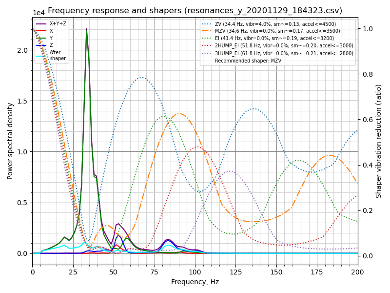
贴合成形器‘zv’频率=34.4HZ(振动=4.0%,平滑~=0.132)。
为避免使用‘zv’进行过多平滑处理,建议使用max_Accel<=4500 mm/秒^2。
贴合成形器‘mzv’频率=34.6hz(振动=0.0%,平滑~=0.170)。
为避免使用‘mzv’进行过多平滑处理,建议使用max_Accel<=3500 mm/秒^2。
贴合成形器‘EI’频率=41.4HZ(振动=0.0%,平滑~=0.188)。
为避免使用‘ei’进行过多平滑处理,建议使用max_Accel<=3200 mm/秒^2。
贴合成形器‘2hump_ei’频率=51.8HZ(振动=0.0%,平滑~=0.201)。
为避免使用‘2hump_ei’时过于平滑,建议使用max_Accel<=3000 mm/秒^2。
成型器‘3hump_ei’频率=61.8HZ(振动=0.0%,平滑~=0.215)。
为避免使用‘3hump_ei’时过于平滑,建议使用max_Accel<=2800 mm/秒^2。
推荐的整形器为mzv@34.6 hz
推荐的配置可以添加到[input_shaper]的printer.cfg分段中,例如:
[输入整形器]。
造型频率x:...。
Shaper_type_x:...。
Shaper_freq_y:34.6。
Shaper_type_y:mzv。

[打印机]。
Max_Accel:3000#不应超过X和Y轴的估计max_Accel
也可以根据生成的图表自己选择一些其他配置:图表上的功率谱密度的峰值对应于打印机的共振频率。
Note that alternatively you can run the input shaper auto-calibration from Klipper directly, which can be convenient, for example, for the input shaper re-calibration.
平行于喷嘴移动打印床的打印机
如果打印机的打印床可以平行于喷嘴移动,测量X和Y轴时需要改变加速度计的安装位置。安装加速度计到打印头以测量X轴共振,安装到打印床以测量Y轴(该类打印机的常见配置)。
However, you can also connect two accelerometers simultaneously, though the ADXL345 must be connected to different boards (say, to an RPi and printer MCU board), or to two different physical SPI interfaces on the same board (rarely available). Then they can be configured in the following manner:
[adx1345 HOTEND]。
#假设`hotend`芯片连接到RPI。
CS_PIN:RPI:无。

[adx1345张床]。
#假设`bed`芯片连接到打印机MCU板。
CS_PIN:...#打印板SPI芯片选择(CS)针脚。

[共振测试仪]。
#假设床吊杆打印机的典型设置。
加速芯片_x:adx1345主机。
Accel芯片y:adx1345床。
探测点:...
Two MPUs can share one I2C bus, but they cannot measure simultaneously as the 400kbit/s I2C bus is not fast enough. One must have its AD0 pin pulled-down to 0V (address 104) and the other its AD0 pin pulled-up to 3.3V (address 105):
[mpu9250 hotend]
i2c_mcu: rpi
i2c_bus: i2c.1
i2c_address: 104 # This MPU has pin AD0 pulled low

[mpu9250 bed]
i2c_mcu: rpi
i2c_bus: i2c.1
i2c_address: 105 # This MPU has pin AD0 pulled high

[resonance_tester]
# Assuming the typical setup of the bed slinger printer
accel_chip_x: mpu9250 hotend
accel_chip_y: mpu9250 bed
probe_points: ...
[Test with each MPU individually before connecting both to the bus for easy debugging.]
然后,命令TEST_RESONANCES AXIS=X和TEST_RESONANCES AXIS=Y会使用每个轴相应的加速度计。
最大平滑度
请注意,输入整形器会在使一些打印的路径被平滑。由执行calibrate_shaper.py脚本或SHAPER_CALIBRATE命令自动得出的输入整形器会尽量不加剧平滑的同时试图最小化产生的振动。脚本可能会得出不是最优的整形器的频率,或者你可能希望以更强的剩余振动为代价来减少平滑度。在这些情况下,可以要求脚本限制输入整形器的最大平滑度。
参考以下自动调谐结果:
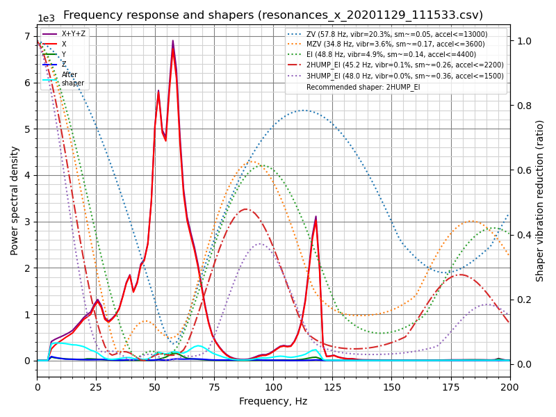
Fitted shaper 'zv' frequency = 57.8 Hz (vibrations = 20.3%, smoothing ~= 0.053)
To avoid too much smoothing with 'zv', suggested max_accel <= 13000 mm/sec^2
Fitted shaper 'mzv' frequency = 34.8 Hz (vibrations = 3.6%, smoothing ~= 0.168)
To avoid too much smoothing with 'mzv', suggested max_accel <= 3600 mm/sec^2
Fitted shaper 'ei' frequency = 48.8 Hz (vibrations = 4.9%, smoothing ~= 0.135)
To avoid too much smoothing with 'ei', suggested max_accel <= 4400 mm/sec^2
Fitted shaper '2hump_ei' frequency = 45.2 Hz (vibrations = 0.1%, smoothing ~= 0.264)
To avoid too much smoothing with '2hump_ei', suggested max_accel <= 2200 mm/sec^2
Fitted shaper '3hump_ei' frequency = 48.0 Hz (vibrations = 0.0%, smoothing ~= 0.356)
To avoid too much smoothing with '3hump_ei', suggested max_accel <= 1500 mm/sec^2
Recommended shaper is 2hump_ei @ 45.2 Hz
请注意,报告的 smoothing(平滑)值是抽象的预测值。这些值可用于比较不同的配置:值越高,整形器造成的平滑度就越高。但是,这些平滑值并不表示任何实际的平滑度的量,因为实际的平滑取决于max_accel和square_corner_velocity参数。因此,如果希望了解所选配置造成的实际平滑效果,需要打印一些测试件。
在上面的示例中,脚本给出了不错的整形器参数建议,但是如果想在 X 轴上减少平滑度,就需要尝试使用以下命令限制脚本挑选参数时的整形器平滑值极限:
~/klipper/scripts/calibrate_shaper.py /tmp/resonances_x_*.csv -o /tmp/shaper_calibrate_x.png --max_smoothing=0.2
这将平滑值限制在0.2。现在可以得到以下结果:
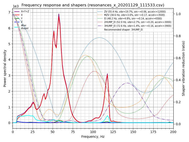
Fitted shaper 'zv' frequency = 55.4 Hz (vibrations = 19.7%, smoothing ~= 0.057)
To avoid too much smoothing with 'zv', suggested max_accel <= 12000 mm/sec^2
Fitted shaper 'mzv' frequency = 34.6 Hz (vibrations = 3.6%, smoothing ~= 0.170)
To avoid too much smoothing with 'mzv', suggested max_accel <= 3500 mm/sec^2
Fitted shaper 'ei' frequency = 48.2 Hz (vibrations = 4.8%, smoothing ~= 0.139)
To avoid too much smoothing with 'ei', suggested max_accel <= 4300 mm/sec^2
Fitted shaper '2hump_ei' frequency = 52.0 Hz (vibrations = 2.7%, smoothing ~= 0.200)
To avoid too much smoothing with '2hump_ei', suggested max_accel <= 3000 mm/sec^2
Fitted shaper '3hump_ei' frequency = 72.6 Hz (vibrations = 1.4%, smoothing ~= 0.155)
To avoid too much smoothing with '3hump_ei', suggested max_accel <= 3900 mm/sec^2
Recommended shaper is 3hump_ei @ 72.6 Hz
新的参数与之前的建议比,振动要大一些,但平滑度明显比之前小,允许打印时更高的极限加速度。
在选择 max_smoothing 参数时,可以使用试错的方法。试试几个不同的值并对比得到的结果。请注意,输入整形器产生的实际平滑效果主要取决于打印机的最低谐振频率:最低谐振的频率越高,平滑效果越小。因此,如果要求脚本找到一个具有不切实际小平滑度的输入整形器配置,它将以增加最低共振频率的振纹为代价(通常,这在打印件中比平滑产生的影响更明显)。因此,一定要仔细检查脚本所报告的预计剩余振动,确保它们不会太高。
注意,如果为两个轴选择了一个相同的 max_smoothing 值,可以把它存储在 printer.cfg 为
[resonance_tester]
accel_chip: ...
probe_points: ...
max_smoothing: 0.25  # an example
如果在将来使用SHAPER_CALIBRATE Klipper命令重新运行输入整形器自动调谐,它将使用存储的max_smoothing 值作为参考。
选择 max_accel
由于输入整形器会在打印件中产生一些平滑,特别是在高加速时,选择一个不会产生过多平滑的max_accel 依然很重要校准脚本为max_accel 参数提供了一个不应该产生过多平滑的估计值。请注意,由校准脚本显示的max_accel 只是一个理论上的最大值,在这个值上,各自的整形器仍然能够工作而不产生过多的平滑。这决不是建议设置的打印加速度。你的打印机能够承受的最大加速度取决于它的机械性能和所用步进电机的最大扭矩。因此,建议在[printer] 部分设置max_accel 时不要超过X轴和Y轴的估计值,并保守一些。
或者,按照这个章节的输入整形器调整指南,打印测试模型,通过实验选择max_accel 参数。
同样的通知也适用于带有SHAPER_CALIBRATE 命令的输入整形器自动校准:在自动校准后仍需选择正确的max_accel 值,建议的加速度限制将不会被自动应用。
Keep in mind that the maximum acceleration without too much smoothing depends on the square_corner_velocity. The general recommendation is not to change it from its default value 5.0, and this is the value used by default by the calibrate_shaper.py script. If you did change it though, you should inform the script about it by passing --square_corner_velocity=... parameter, e.g.
~/klipper/scripts/calibrate_shaper.py /tmp/resonances_x_*.csv -o /tmp/shaper_calibrate_x.png --square_corner_velocity=10.0
so that it can calculate the maximum acceleration recommendations correctly. Note that the SHAPER_CALIBRATE command already takes the configured square_corner_velocity parameter into account, and there is no need to specify it explicitly.
如果重新校准一个整形器,并且建议的整形器配置的报告平滑度与你在以前的校准中得到的几乎相同,这个步骤可以被跳过。
Unreliable measurements of resonance frequencies
Sometimes the resonance measurements can produce bogus results, leading to the incorrect suggestions for the input shapers. This can be caused by a variety of reasons, including running fans on the toolhead, incorrect position or non-rigid mounting of the accelerometer, or mechanical problems such as loose belts or binding or bumpy axis. Keep in mind that all fans should be disabled for resonance testing, especially the noisy ones, and that the accelerometer should be rigidly mounted on the corresponding moving part (e.g. on the bed itself for the bed slinger, or on the extruder of the printer itself and not the carriage, and some people get better results by mounting the accelerometer on the nozzle itself). As for mechanical problems, the user should inspect if there is any fault that can be fixed with a moving axis (e.g. linear guide rails cleaned up and lubricated and V-slot wheels tension adjusted correctly). If none of that helps, a user may try the other shapers from the produced list besides the one recommended by default.
自定义测试轴
TEST_RESONANCES命令支持自定义轴。虽然这对输入整形器校准并不真正有用,但它可用于深入研究打印机共振,并检查皮带张力等。
要检查CoreXY打印机上的皮带张力,请执行
TEST_RESONANCES AXIS=1,1 OUTPUT=raw_data
TEST_RESONANCES AXIS=1,-1 OUTPUT=raw_data
并使用graph_accelerometer.py处理生成的文件,例如.
~/klipper/scripts/graph_accelerometer.py -c /tmp/raw_data_axis*.csv -o /tmp/resonances.png
以生成/tmp/resonances.png,对比共振的数据。
对标准构型的三角洲打印机(A塔~210°,B塔~330°,C塔~90°),执行
TEST_RESONANCES AXIS=0,1 OUTPUT=raw_data
TEST_RESONANCES AXIS=-0.866025404,-0.5 OUTPUT=raw_data
TEST_RESONANCES AXIS=0.866025404,-0.5 OUTPUT=raw_data
然后使用同样的命令
~/klipper/scripts/graph_accelerometer.py -c /tmp/raw_data_axis*.csv -o /tmp/resonances.png
以生成/tmp/resonances.png,对比共振的数据。
输入整形器自动校准
除了为输入整形器功能手动选择适当的参数外,还可以直接从Klipper运行输入整形器的自动调谐。通过Octoprint终端运行以下命令:
SHAPER_CALIBRATE
这将为两个轴运行完整的测试,并生成用于频率响应和建议的输入整形器的csv输出(默认为/tmp/calibration_data_*.csv )。在Octoprint中会提示控制台每个输入整形器的建议频率,以及为这台打印机推荐的输入整形器。例如:
Calculating the best input shaper parameters for y axis
Fitted shaper 'zv' frequency = 39.0 Hz (vibrations = 13.2%, smoothing ~= 0.105)
To avoid too much smoothing with 'zv', suggested max_accel <= 5900 mm/sec^2
Fitted shaper 'mzv' frequency = 36.8 Hz (vibrations = 1.7%, smoothing ~= 0.150)
To avoid too much smoothing with 'mzv', suggested max_accel <= 4000 mm/sec^2
Fitted shaper 'ei' frequency = 36.6 Hz (vibrations = 2.2%, smoothing ~= 0.240)
To avoid too much smoothing with 'ei', suggested max_accel <= 2500 mm/sec^2
Fitted shaper '2hump_ei' frequency = 48.0 Hz (vibrations = 0.0%, smoothing ~= 0.234)
To avoid too much smoothing with '2hump_ei', suggested max_accel <= 2500 mm/sec^2
Fitted shaper '3hump_ei' frequency = 59.0 Hz (vibrations = 0.0%, smoothing ~= 0.235)
To avoid too much smoothing with '3hump_ei', suggested max_accel <= 2500 mm/sec^2
Recommended shaper_type_y = mzv, shaper_freq_y = 36.8 Hz
如果认同建议的参数,现在可以执行SAVE_CONFIG 来保存设置并重新启动Klipper。 请注意,这不会更新[printer] 分段中的max_accel值。应该按照选择max_accel章节中的注意事项手动更新它。
如果你的打印机热床水平移动,可以选择测试的轴,这样就可以在测试之间改变加速度计的安装点(默认情况下,测试会同时对两个轴一起进行):
SHAPER_CALIBRATE AXIS=Y
可以在校准每个轴之后执行SAVE_CONFIG。
然而,如果同时连接了两个加速度计,只需要运行SHAPER_CALIBRATE ,而不指定轴,就可以一次性校准两个轴的输入整形器。
重新校准输入整形器
SHAPER_CALIBRATE 命令也可以用来在将来重新校准输入整形器,特别是当打印机发生了一些可能影响其运动学的变化时。可以使用SHAPER_CALIBRATE 命令重新进行全面校准,或者通过提供AXIS= 参数将自动校准限制在一个轴上,例如
SHAPER_CALIBRATE AXIS=X
Warning! It is not advisable to run the shaper auto-calibration very frequently (e.g. before every print, or every day). In order to determine resonance frequencies, auto-calibration creates intensive vibrations on each of the axes. Generally, 3D printers are not designed to withstand a prolonged exposure to vibrations near the resonance frequencies. Doing so may increase wear of the printer components and reduce their lifespan. There is also an increased risk of some parts unscrewing or becoming loose. Always check that all parts of the printer (including the ones that may normally not move) are securely fixed in place after each auto-tuning.
此外,由于测量中的一些噪音,每次校准得到的调谐结果会略有不同。不过,这些噪音一般不会对打印质量产生太大影响。然而,我们仍然建议仔细检查建议的参数,并在使用前打印一些测试件以确认它们是正确的。
离线处理加速计数据
可以生成原始的加速度计数据并离线处理(例如在一台电脑上),以查找共振频率为例,在Octoprint的终端内运行如下命令:
SET_INPUT_SHAPER SHAPER_FREQ_X=0 SHAPER_FREQ_Y=0
TEST_RESONANCES AXIS=X OUTPUT=raw_data
忽略SET_INPUT_SHAPER命令的任何错误。对TEST_RESONANCES指定测试的方向。原始数据保存至/tmp目录内。
在一些正常的打印机活动中,也可以通过运行命令 ACCELEROMETER_MEASURE两次来获得原始数据——首先是开始测量,然后是停止测量并写入输出文件。有关更多详细信息,请参阅G-Codes。
这些数据可在以后通过scripts/graph_accelerometer.py和scripts/calibrate_shaper.py`脚本进行处理,在不同的工作模式下,两种脚本支持一个或多个原始数据csv文件作为输入。graph_accelerometer.py支持以下几种模式:
- 绘制原始加速度数据图(使用
-r参数),仅支持一个输入; - 绘制频率响应图(无需额外参数),如果指定了多个输入文件,将计算他们的平均值;
- 在多个输入之间比较频率响应曲线(使用
-c参数);通过-ax,-ay或-az`参数,可以额外指定哪个轴参与比较(在未指定时将计算所有轴振动的总和); - 绘制频谱图(使用
-s参数),只支持1个输入;您可以通过-a x、-a y或-a z参数指定考虑哪个加速度计轴(如果不指定,则取所有轴的振动总和)。
请注意,graph_accelerometer.py脚本仅支持RAW_DATA*.csv文件,不支持共振*.csv或CALIBRATION_DATA*.csv文件。
例如,
~/klipper/scripts/graph_accelerometer.py /tmp/raw_data_x_*.csv -o /tmp/resonances_x.png -c -a z
将绘制Z轴的几个/tmp/raw_data_x_*.csv文件与/tMP/Resonance_x.png文件的比较。
Shaper_calbrate.py脚本接受1个或多个输入,可以运行输入整形器的自动调优,并建议适合所有提供的输入的最佳参数。它会将建议的参数打印到控制台,如果提供了-o output.png参数,则可以额外生成图表;如果指定了-c output.csv参数,则可以额外生成CSV文件。
如果运行输入整形器的一些高级调优,向shaper_calbrate.py脚本提供几个输入可能会很有用,例如:
- 在第一次将加速度计连接到刀头、第二次将加速度表连接到床的床甩油机打印机上,对单个轴运行两次
TEST_RESONANCES AXIS=X OUTPUT=raw_data(和Y轴),以检测轴的交叉共振,并尝试用输入整形器消除它们。 - 在具有玻璃床和磁性表面(较轻)的甩床器上运行两次
TEST_RESONANCES AXIS=Y OUTPUT=raw_data,以找到适用于任何打印表面配置的输入整形器参数。 - 组合来自多个测试点的共振数据。
- 组合来自2个轴的共振数据(例如,在床吊杆打印机上配置X轴INPUT_SHAPER从X轴和Y轴共振,以消除床的振动,以防喷嘴在X轴方向上移动时‘捕捉’到印刷品)。